
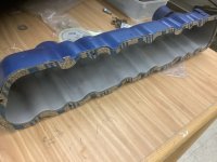
X2 Good catch drag-200stang you are certainly correct that enforcement Ring should only be used on a Auto Trans Flex Plate it would never be needed on any of the Manual Trans Flywheels. I was looking at the flywheel bolts they show signs of rubbing on something my guess was it was on the Original Clutch Disk, yet I didn't see that Ring on there, maybe it was because of its color in the picture that Reinforcement Ring makes the Flywheel bolts stick up to high. LOL, but I do see the ring now after you motioned it. If you still can I would say you should remove that Ring so it doesn't tear up your Clutch Disk Anti Chatter Springs as well as cause some extra unnecessary noises. Since they used the Auto Trans Flex Plate Reinforcement Ring, this makes me think the the Car might of had an Auto Trans in it before and they might of also used the shorter Flex Plate Crankshaft mounting bolts if so they would be too short in length. The Flywheel bolts are 7/16 in. x 20 with a under head length of 0.900 in. to 1.00. The Auto Flex plate bolts are also 7/16 in. x 20 with I think a under head length of 5/8 inch to maybe 3/4 inch length.I have never had an 8.5 dog dish flywheel, but I do not think that the flex plate reinforcer ring goes with the fly wheel. For what you are doing as long as you have good thread engagement, I would not worry about it.
If someone knows for sure that ford did that on 8.5 flywheels, I will edit this post. Just do not want people thinking that they are missing it when they see it in pics.
You are using an out of date browser. It may not display this or other websites correctly.
You should upgrade or use an alternative browser.
You should upgrade or use an alternative browser.
All Small Six 200 6 rebuild steps
- Thread starter adobejoe
- Start date
This relates to all small sixes
Wow, glad you experts are here to set me straight. I will remove that spacer ring and toss in the parts bin. A bit of a PITA because I used threadlocker when I put the six bolts on yesterday, but better get it right now rather then have some damn'd chatter after it is all together and running. That would be even more annoying. Thanks for the catch!
Yeah, I assumed it did, but do you know if it came from ford like that, or did it have an auto. before and they just put in on the flywheel from the flex plate.
That is so it can only go on one place, so if you balance the crank and then install the flywheel and balance together it has to go on the same next time it is apart.
That is so it can only go on one place, so if you balance the crank and then install the flywheel and balance together it has to go on the same next time it is apart.
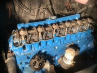
Yeah, I am figuring things out a bit now. The door tag shows it originally was a 200 six with a 3 speed manual. When I bought the car in early 80's the previous owner said they had put in a 200 six out a 68 mustang. They must of installed the 4 speed dagenham, but they used the original 3 speed shifter, and I never really realized it was a 4 speed, just that it was hard to shift at times. It also made some chatter and I think I replaced the clutch once. When I disassembled and replaced synchros and a gear in the transmission I realizedthe tranny was definitely a 4-speed. That spacer ring must of been there from an automatic on the swapped 68 engine, is all I can figure. But would they have used the dog dish on an automatic? Bubba is right there is a little wear on the bolt heads, likely from the clutch springs. The rear end was also replaced, I believe a 1970 maverick. I think it has a 1:2.83 rear ratio. I guess I should call it a frankenstang!
Yeah I am sure Sorry about that if drag-200stang hadn't see the Reinforcement Ring on there I sure didn't noticed it this makes the second time that I know of on the site that there was a Auto Trans Flex Plate Ring installed on a Flywheel there has probably been many more. You might hang on to the Ring though there might be someone that doing a Auto Trans swap I have seen a few that were put them together without that Reinforcement Ring and also used the much to Long of Flywheel Mounting Bolts.I will remove that spacer ring and toss in the parts bin. A bit of a PITA because I used threadlocker when I put the six bolts on yesterday, but better get it right now rather then have some damn'd chatter after it is all together and running. That would be even more annoying. Thanks for the catch!
So you were able to find the right 4 speed shifter for your Dagenham than from your pictures that must of took some doing to find. No you wouldn't be able to use the Dog Dish Flywheel with an Automatic Trans it wouldn't allow a Torque Converter to fit in the Bell Housing and bolt up. Your probably right that the 1968 Engine might of had a C4 Auto Trans on it before the swap into your car. Be sure you measure the length of the Crankshaft mounting bolts or post a picture of them when you get it apart again. you should be able to get a new set of Flywheel bolts at your locale Auto Parts if you need them from Doormen. Your doing great, keep up the good work.Yeah, I am figuring things out a bit now. The door tag shows it originally was a 200 six with a 3 speed manual. When I bought the car in early 80's the previous owner said they had put in a 200 six out a 68 mustang. They must of installed the 4 speed dagenham, but they used the original 3 speed shifter, and I never really realized it was a 4 speed, just that it was hard to shift at times. It also made some chatter and I think I replaced the clutch once. When I disassembled and replaced synchros and a gear in the transmission I realizedthe tranny was definitely a 4-speed. That spacer ring must of been there from an automatic on the swapped 68 engine, is all I can figure. But would they have used the dog dish on an automatic? Bubba is right there is a little wear on the bolt heads, likely from the clutch springs. The rear end was also replaced, I believe a 1970 maverick. I think it has a 1:2.83 rear ratio. I guess I should call it a frankenstang!
Yes I was able to track down the right shift linkage and the Original type chrome shifter on eBay. Had to order transmission gears and synchro from an outfit in England. Measure one of those bolts, right at 1 inch so I will attach the dog dish again. Then carefully center the new clutch disk and pressure plate, and finally attach transmission. This project has been 2+ yrs of on the side construction. Likely never should of taken it on given the body condition…..oh well live and learn
Attachments
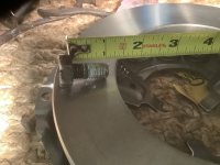
Very good those are the correct Bolts for a Flywheel!
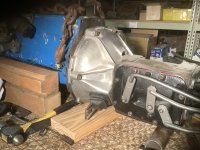
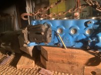
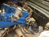
Transmission coupled! I was very careful to center the clutch plate and used just a very small dab of grease on pilot bearing. I think where the pencil point should be an oil pressure sender or switch? Hope to drop in next week. Stay tuned,
Attachments

Hello Adobejoe. This is my first post. Have enjoyed following along with your rebuild keep up the good work. Could I please ask you to pm the details of where you got your genuine ford 200ci rear main seal as I need one for my 66 coupe. Either that or maybe bubba23499 as I believe he asked as well?Transmission coupled! I was very careful to center the clutch plate and used just a very small dab of grease on pilot bearing. I think where the pencil point should be an oil pressure sender or switch? Hope to drop in next week. Stay tuned,
Many thanks and have a nice day.
Excellent on the trans mounting. For the Oil Pressure Switch / Sender its located on the other side of the Short Block just in front of the Bell Housing about Mid way between the Oil Pan Rail to the Blocks Deck surface. Good luck on the install.Transmission coupled! I was very careful to center the clutch plate and used just a very small dab of grease on pilot bearing. I think where the pencil point should be an oil pressure sender or switch? Hope to drop in next week. Stay tuned,
What Bubba said, and your pencil is the block water drain.
Engine went in smooth smoothly! Little worried because I kept shift linkage attached but easy Peary! I think it would of been harder with the head attached with that additional weight and will just be careful getting it installed. No sealer on the head gasket I presume?
Attachments
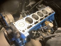
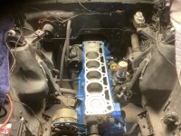
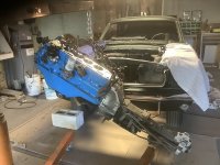
If you are using an Original Steel type Head Gasket then you would need something like Copper Coat on it. If its a newer type Composition type Head Gasket then right no sealer is needed. The rebuilt Engine looks great setting in the Mustang's engine bay, good job!
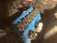
Looking great adobejoe, won't be long until its ready to run again. There were several of The Ford small six engines that used the Adjustable Rocker Arms stock like all of the 144's, and some early built 170's & 200's up to about 1965. Many also will swap on the adjustable Rocker Arms from the early engines to use on the 200's & 250's its a simple bolt on job if you can find some. The Adjustable Rocker Arms are a 1.5 to 1 Ratio the same as your non Adjustable Rocker Arms, there are also some 1.6 to 1 available that are custom made from the stock 1.5 to 1's adjustable Rocker Arms for a nice performance increase. Keep going!
Lookin' good! . . remember to squirt some oil before closin' it up. Pre-priming with the pump will be best.Plugging away. Head mounted with composition gasket, the push rods, and then rockers. I know some valves can be adjusted, but apparently not on the 200 six?
On the valve cover gasket looks like I use gasket cement,sealer on the head side but what about top side? Nothing? I do not want a. Leak. Maybe black silicon?
Attachments
The way I have been doing it for a long time is to use some Permatex Aviation Cement or the old GasgacinchOn the valve cover gasket looks like I use gasket cement,sealer on the head side but what about top side? Nothing? I do not want a. Leak. Maybe black silicon?
to glue down the gasket to the Valve Cover. Than you use a good bead of Silicone between The Valve Cover Gasket and the head surface that way if you ever need to pull the Valve the Valve Cover Gasket will last for 2 to 3 times before needing to be replaced again and you just use some more Silicone to reseal it. Good Luck
So I just realized another snafu. My exhaust kit I bought is the standard 1 3/4” system from tailpipe to manifold. But this engine is out of a 1968 and appears to be a 2” exit flange. I suppose I may make it work with the donut gasket, but my bigger concern will be diminished performance due to less air flow. Well, not much I can do about it now. Any ideas?