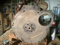
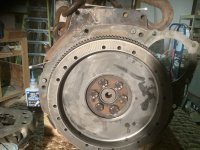
Got it thanks, I attached flywheel and noticed the backing or spacer plate does not meet for several threaded holes in the block, up high. See picture. I assume this engine was designed for heavier tranny or at least a larger bell housing? When I bought the car in the early 1980s. They told me they replaced original engine with 200 six out of a 1968 Ford. The car is a 1965 mustang and I am guessing the dagenham tranny was original. They had cobbled on a 3 speed shifter, which I have changed over to 4 speed. I am guessing I drove it all those years (over 80k miles). Using 2-4 gears. Lucky I did not fry the drivetrain!