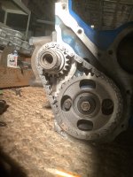
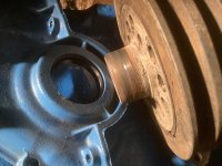
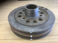
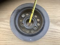
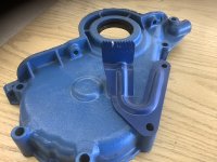
That's some really great detective work being able find the Original Ford Part Number Rear Main Seal it will work excellent on all the 144, 170, & 200 Small Six's! Yes that would be the correct way to install them as far as doing the clocking part. However that painted yellow side of that seal would need to be facing towards the back of the engine so that the open side of the seals lip is always to the inside of the engine. That's really up to you if you want to set it in the seal grove using a silicone or gasket cement to glue it in, I don't ever do that. I would also have think that any extra thickness of material in the grove would put a little extra pressure on the seals edge that's touching on rubbing on the crankshaft surface. I only make sure the Blocks and the Rear Main Caps Grove is clean of and Dirt, Grease, or any other Crud, wire brush it out then install the seal and clock it then its a done deal. The OEM seals I have removed were also like that though the early ones were not clocked. The only Ford Tech Bulletin that I know of on these type Rear Main Seals was only about Clocking them in the Grove. If your very worried its going to leak (It really shouldn't since its the right main seal) I guess after its installed completely with rear main cap bolted down to the torque spec. If you wanted to I guess you could go around the outside of that seal and the grove (at the Back of the block) using a very small bead of the Silicone from that outer grove of the block bridging over to the side of the seal use your finger to smooth it and push it into that outer grove, again I never did that either. Good luck If you don't mind PM me with that info on how to get those Rear Main Seals.