Been thinking of this for quite awhile now. I would like to learn what it takes to come up with the best Hot Side design this is going to be just for Drag Racing only in a very light weight car. Would this be a be a Single, Twin, or Compound Turbo system? Engine is going to be a 1958 to 1964 Ford 223 to 262 Six with an C4 Auto Trans. I think I understand the Cold side but would also like to come up with the best system there too. Thank you
You are using an out of date browser. It may not display this or other websites correctly.
You should upgrade or use an alternative browser.
You should upgrade or use an alternative browser.
What Would be the Best of the Turbo Design's for Strictly a Drag Race Car?
- Thread starter bubba22349
- Start date
The challenge in drag racing is to get launch boost in time to leave.
If you stage last, you may only have 2 to 3 seconds from when you stage to launch.
We all used twin turbochargers to minimize spool time.
We used a three step rev limiter so the car could brake into the staging lights under WOT using a low rpm limiter, then set the transbrake with the next step limiter to get launch boost then launch.
This allowed us to begin building boost early.
The fastest spooling will be with twin turbochargers.
Cylinders 1,2 and 3 will drive one turbo while 4,5 and 6 drive the second.
The primary pipes need to be long enough so they can be near equal length.
The challenge for us and our competitors was, we were making at least 5 hp per cu in using very large cams with a lot of overlap.
There wasn't any significant power below 4000 rpm.
You might not have the same problem with a 262 six but you asked for the best "Hot Side" configuration, so I gave you what I know from experience to start this conversation.
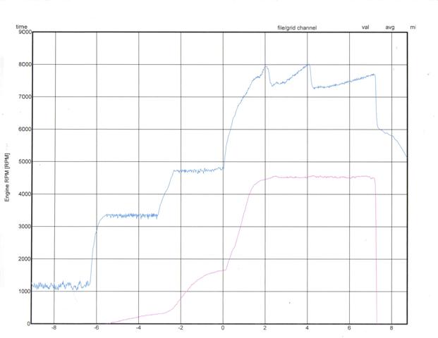
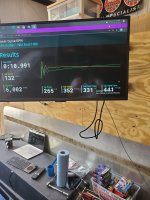
Below shows our 7.03 sec 1/4 mile run.
Each horizontal line represents 5 lbs of boost as well as 1000 rpms.
The launch was at 8 lbs of boost and the run was at 25 lbs. of boost shown by the lower graph
If you stage last, you may only have 2 to 3 seconds from when you stage to launch.
We all used twin turbochargers to minimize spool time.
We used a three step rev limiter so the car could brake into the staging lights under WOT using a low rpm limiter, then set the transbrake with the next step limiter to get launch boost then launch.
This allowed us to begin building boost early.
The fastest spooling will be with twin turbochargers.
Cylinders 1,2 and 3 will drive one turbo while 4,5 and 6 drive the second.
The primary pipes need to be long enough so they can be near equal length.
The challenge for us and our competitors was, we were making at least 5 hp per cu in using very large cams with a lot of overlap.
There wasn't any significant power below 4000 rpm.
You might not have the same problem with a 262 six but you asked for the best "Hot Side" configuration, so I gave you what I know from experience to start this conversation.
Below shows our 7.03 sec 1/4 mile run.
Each horizontal line represents 5 lbs of boost as well as 1000 rpms.
The launch was at 8 lbs of boost and the run was at 25 lbs. of boost shown by the lower graph
Last edited:
Thank you pmuller9, I appreciate your wisdom. That twin Turbo set up should not be that hard to build for front and rear 3 cylinder groups and make into equal lengths. I was thinking that the Boost would be around 15 to 18 Lbs. I do wonder how much the Head Gasket would be able to handle up to, the only Turbo 223 / 262's I have herd of were only Street type systems running about 8 Lbs that then kicked out a stock rod or took out the Head Gasket at just over 10 Lbs. Good set of Rods and Custom forged Pistons should fix that first problem. What size pair of Turbos do you think it would need.
The turbo size depends on the max rpm and volumetric efficiency.
Looking at a 223, If you port the head to get closer to 200 cfm and run the engine out to 5000 rpm, you are looking at twin turbochargers with 38 to 40mm compressor inducers.
That's with a good intercooler. You could eliminate the intercooler if you run E85 or Methanol
It should get you around 400 hp with 18 to 20 lbs of boost.
Would you be bracket racing against an ET?
Would you be allowed to use a delay box for launch?
Last edited:
Mydogisshaggy
Well-known member
38mm and 40mm is what the Ecoboost 3.5 run... Plenty of those around., Do the other specs on those seem like a good match? Seems like a good middle ground between eBay turbos and aftermarket for the price differences.The turbo size depends on the max rpm and volumetric efficiency.
Looking at a 223, If you port the head to get closer to 200 cfm and run the engine out to 5000 rpm, you are looking at twin turbochargers with 38 to 40mm compressor inducers.
That's with a good intercooler. You could eliminate the intercooler if you run E85 or Methanol
It should get you around 400 hp with 18 to 20 lbs of boost.
Would you be bracket racing against an ET?
Would you be allowed to use a delay box for launch?
Sorry pmuller9, for not getting back to this sooner got tied up in some work all day today. Here is some old Flow numbers on the 223 Heads the 1957 to 1960 are also very good flowing with a little bit smaller combustion Chambers. The 1961 to 1964 262 Head is supposed to be even better yet I have some pictures of one Persons Porting but work but no Flow numbers on it. With all these heads the Exhaust Ports flow can be equaled pretty easy into a D Port shape. The issue is to get the Intake Ports to flow equally they are round at the Intake Flange. There are two Single Ports and then two Siamese Ports getting the right size so that they all flow the same is something that probably will need a Flow bench to do I haven't had access to one for many years. I do think that its not to hard to get over 200 CFM on the Intakes maybe up to a 230 or 235 range with the right size Intake Valve in the range of 1.84 to 1.90 and a little Combustion Chamber Work with a High Lift Cam of over .400 the Bores need to be notched too. I like the Idea of a 262 Block with its much Larger Bore size and if I still knew anyone that did Furnace brazing I would consider do bigger size Sleeves to get Bore size close to 4.00 Inch. I am also wondering if the cranks rod Throws could be cut down to 2.10 or 2.00 inch to slow down the Rod Bearing Speed some.The turbo size depends on the max rpm and volumetric efficiency.
Looking at a 223, If you port the head to get closer to 200 cfm and run the engine out to 5000 rpm, you are looking at twin turbochargers with 38 to 40mm compressor inducers.
That's with a good intercooler. You could eliminate the intercooler if you run E85 or Methanol
It should get you around 400 hp with 18 to 20 lbs of boost.
Would you be bracket racing against an ET?
Would you be allowed to use a delay box for launch?
Ford 6-4U said Here are the flow numbers for the 61-64 223 FORD small chamber head with 1.78 intake 1.51 exhaust.
Air flow is @ 28" test pressure.
Intake CFM
.100"=56
.200"=115
.300"=150
.400"=153
.500"=156
Stock Exhaust peaks at 115
These flow numbers are for a 223 small chamber head 1.84 intake 1.6 exhaust. This head has been race ported and currently holds the SCTA xo/production record, in a 53 FORD @ 135.530 mph. I post these numbers only to encourage others to get the most out of there Vintage FORD engine.
Intake CFM With a radius inlet.
.100"=70
.200"=128
.300"=167
.400"=187
.500"=200
Exhaust CFM No pipe or header.
.100"=57
.200"=100
.300"=120
.400"=132
.500"=138
On the Bottom Lines are some Intake 223 Flow Numbers in Yellow & Orange. For a stock 223 Exhaust in Yellow


Ford 6-4U said "The 223 can holds it own against the vintage sixes. I was very conservative with the exhaust figures. With a pipe installed on the head the 1.6 exhaust valve will flow 163 CFM @ 28" .500" lift. With a Clifford header installed it drops to 140 CFM @ 28". I have found no need to run more exhaust duration than intake on this engine. With 292 intake/exhaust duration, I have seen no exhaust gas residue in the intake port or bowl."
At around 400 H.P. form 18 to 20 Lbs. of Boost would make for a very fun and Quick Ride in a light Altered Roadster of around 1700 to 2000 Lbs I know were a Rough mid 1925 Essex Six 2 door Sedan body and some rough Ford T body's. Or maybe a gutted out Early Falcon Coupe at about that same weight (there is also a 61 Body shell not to far from here no front clip though). Yes I would for sure like to to be able Bracket Race it that also the reason for the C4 or maybe a different Auto Trans to try and be as consistent as possible on the Dial In. Maybe need to also figure out a car that fits with. I don't know which brackets will let you run a delay box for launch but wanted to use use a trans brake so maybe they would allow it. I mostly only did foot brake brackets with no electronics before.
Bubba, Great Info!
Was the 223 head intake flow numbers through the Single or Siamese intake ports?
I spent a lot of time working with the Buick S8 which has 4 Siamese intake ports.
The Siamese ports do not provide equal cylinder fill to the adjacent cylinders because of the intake cycle timing.
When the Salt Flats crew tried to turbocharge, they would lose the cylinders that were lean.
I worked with another S8 project trying to get port injection to work to no avail.
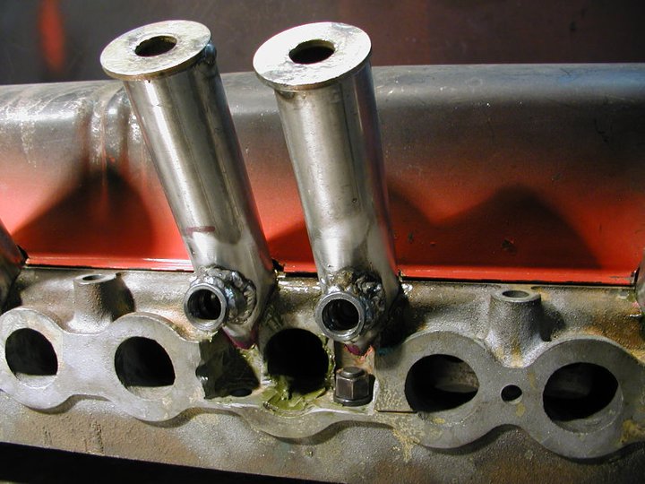
The solution was to convert the head to an 8 single intake port design.
It looks like the most successful Chevy six turbo engines use the Wayne 12 port head for the same reason.
The Montana Salt Flat crew did what they called "Budweiser Engineering" and installed intake tubes directly to the intake valves.
They were able to set several speed records with the Buick S8 engine afterward.
The Ford 223/262 head has both Siamese and Single intake ports which would result in 3 different VEs for the six cylinders.
It also has head bolt interference that was solved above by lowering the bolt seat.
Thoughts?
Was the 223 head intake flow numbers through the Single or Siamese intake ports?
I spent a lot of time working with the Buick S8 which has 4 Siamese intake ports.
The Siamese ports do not provide equal cylinder fill to the adjacent cylinders because of the intake cycle timing.
When the Salt Flats crew tried to turbocharge, they would lose the cylinders that were lean.
I worked with another S8 project trying to get port injection to work to no avail.
The solution was to convert the head to an 8 single intake port design.
It looks like the most successful Chevy six turbo engines use the Wayne 12 port head for the same reason.
The Montana Salt Flat crew did what they called "Budweiser Engineering" and installed intake tubes directly to the intake valves.
They were able to set several speed records with the Buick S8 engine afterward.
The Ford 223/262 head has both Siamese and Single intake ports which would result in 3 different VEs for the six cylinders.
It also has head bolt interference that was solved above by lowering the bolt seat.
Thoughts?
Last edited:
The 223 Flow tests show some real decent results, however I didn't do those Flow tests and don't know about all the details of which ports were tested I would assume that they tested all them but can't verify that. I have also been following a Bonneville Team since sometime last year hearing about them from "CNC Dude". The Team Owner was a site member "johnrodz" and was here for a short time looking for some info on these Ford Six's, most of his posts are located in this link. https://fordsix.com/threads/h-p-engine-build-223-262-l-6.73584/#post-565318
The Truck is a 1961 ford Unibody F100 (I think) has a 262 Six running in the XO/PP Class on his last build don't know exactly what size the bore is or the Stroke, my guess is it has a 262 stock stroke of 4.03 with a bore of .050 to .060 over, on on of last his Dyno Run's put him in about the range of 1.3 to 1.4 N.A. H.P per Cu. In. I believe he probably achieved his goal of 1.5 or a little more H.P. per Cu. In. with his last improvements like a different camshaft grind. I have been thinking to try and contact him for more info on his 262 Six experiences if he might share some of them, he is in a very tough class and was trying to best that long standing record. He recently found out that holder of the record had bested it I think this was at end of last year. On April 21, 22 they set a standing 1/2 mile record on their second run, but the engine was also severally Damaged in that pass.
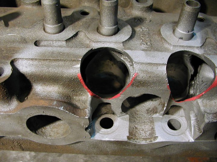
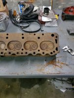
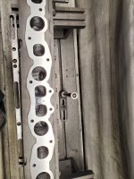
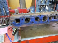
Wow yes that Buick Head Re-Porting is a great Idea too I remember seeing a Bick S8 run at my local strip in later 1960's every so often. The Ford 223 / 262 heads have three Siamese Ports two intakes paired, plus the 3 & 4 ports of the Center Exhaust Manifold are paired kind of like the 200 six but its very easy to fix them. Turning all the Intakes into Single High Ports would be an interesting project.
The Truck is a 1961 ford Unibody F100 (I think) has a 262 Six running in the XO/PP Class on his last build don't know exactly what size the bore is or the Stroke, my guess is it has a 262 stock stroke of 4.03 with a bore of .050 to .060 over, on on of last his Dyno Run's put him in about the range of 1.3 to 1.4 N.A. H.P per Cu. In. I believe he probably achieved his goal of 1.5 or a little more H.P. per Cu. In. with his last improvements like a different camshaft grind. I have been thinking to try and contact him for more info on his 262 Six experiences if he might share some of them, he is in a very tough class and was trying to best that long standing record. He recently found out that holder of the record had bested it I think this was at end of last year. On April 21, 22 they set a standing 1/2 mile record on their second run, but the engine was also severally Damaged in that pass.
Wow yes that Buick Head Re-Porting is a great Idea too I remember seeing a Bick S8 run at my local strip in later 1960's every so often. The Ford 223 / 262 heads have three Siamese Ports two intakes paired, plus the 3 & 4 ports of the Center Exhaust Manifold are paired kind of like the 200 six but its very easy to fix them. Turning all the Intakes into Single High Ports would be an interesting project.
Attachments
-
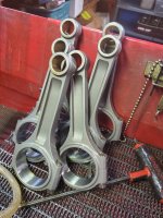 Ford 262 Custom Aftermarket BB Chevy Rods.jpg257.6 KB · Views: 8
 -
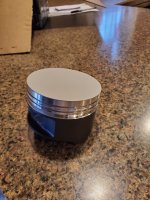 Ford 262 Custom Ross Piston.jpg195 KB · Views: 7
 -
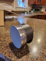 Ford 262 Custom Ross Piston Calico Coated.jpg175.4 KB · Views: 6
 -
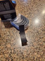 Ford 262 Claico Coated Bearings.jpg281.1 KB · Views: 5
 -
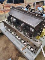
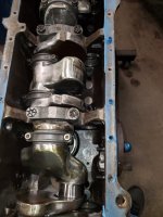 Ford 262 Assembled Bottom End.jpg279.8 KB · Views: 5
 -
 Ford 262 Crank girdle, oil pan, water pump, crank trigger, oil pump. hoses, front motor mount ...jpg395.3 KB · Views: 6
 -
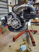
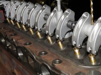
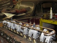
 262 Replacement Head & Ram Intake Finishing Touches 2.jpg235.7 KB · Views: 7
 -
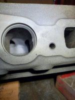 Ford 262 Head Simease Intake Port Before 1.jpg246.4 KB · Views: 7
 -
 Ford 262 Head Simease Intake Port Before 2.jpg169.4 KB · Views: 7
 -
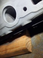
 Stock 262 Head Chamber.jpg194.7 KB · Views: 7
More Pictures of Finished 262 Head
Attachments
-
 262 Replacment Head Finishing Up the Combustion Chamber Shape.jpg269.6 KB · Views: 8
 -
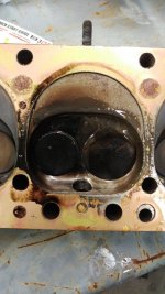 262 Head Finished Combustion Chambers 6.jpg150.3 KB · Views: 6
 -
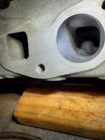 Ford 262 Head Single Intake Port Before 1.jpg203.4 KB · Views: 5
 -
 Ford 262 The Real Dyno Pull Numbers 2.jpg336.8 KB · Views: 6
 -
 Ford 262 Fished Ported Head.jpg257.4 KB · Views: 7
 -
 262 Head Ports 1.JPG200.8 KB · Views: 4
 -
 262 Head Ports 2.JPG135.3 KB · Views: 5
 -
 262 Head Ports 3.JPG187.9 KB · Views: 4
 -
 262 Head Ports 4.JPG177.2 KB · Views: 4
 -
 262 Head Ports 5.JPG177.8 KB · Views: 6
Bubba, Thanks for the pictures
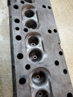
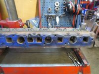
It looks like intake port for 1 and 2 is Siamese along with the intake port for 5 and 6.
Cylinders 3 and 4 have a single intake port.
Siamese intake ports would fill the two cylinders equally if the cylinders were 360 degrees apart in the firing order but that's not the case.
Figuring on a 240 degree intake duration, the intake duration for cylinder 1 follows the intake duration for cylinder 2 just as the #2 intake valve closes. Then there is a 240 degree lull in that Siamese port.
Same with cylinders 5 and 6.
Cylinder 3 and 4 do not share a port so the opening and closing valve port pressures are the same for both.
I would say that the EGTs for cylinders 1,2 and 3 would be relatively different as well as differences between 4,5, and 6.
The EGT spread may be OK for a N/A engine but is problematic for a turbocharged racing engine.
Last edited:
I wonder if there be enough room open them up and put a center plate into the Siamese Ports to divide them equally so they would work. I remember you thinking the BB Chevy rods could work and we were trying to get a deck height measurement, well you were sure right about that. Still have not found out about the Blocks Deck Height or the stock Rod length and Piston Compression Height.
I was thinking that the BBC connecting rods would work.
The piston pin boss clearance would be tightened up so the piston would keep the rod centered on the Crankshaft rod journals.
Something to consider.
We changed to methanol to eliminate engine coolant.
The block can be filled to support any size sleeve you want to install, and you can also fill the head making it easy to make port modifications without the worry of water jacket leakage.
This would also eliminate the need for an intercooler for the turbocharger.
No radiator with a water pump and no intercooler.
Last edited:
The head bolts are on both sides of the Siamese port.I wonder if there be enough room open them up and put a center plate into the Siamese Ports to divide them equally so they would work.
For the Ford 262 Bonneville Race Truck he made an adapter Plate to use a Chevy Power Guide First (No Torque Convertor) that didn't work out to well so he went to a Turbo 350 and a Torque Convertor (Lock Up type Maybe). In searching for more power he then went to a Camaro WC T5 Trans, this is the link to that above Dyno Run after the T5 and Freshened up 262 Engine, Edited.
 Sure sounds Healthy!
Sure sounds Healthy!Attachments

I don't have a 262 yet and have been looking for quite awhile. I think that all the 262's that were used in the bigger trucks would of had a Forged Steel crankshaft, the only one I don't' know as much about is the optional 262 that was offered in the 1964 F100's my guess is that it was also a Steel Crank but I don't know for sure. All the big truck Engines had a Gear driven Camshaft like the 240 / 300 six with fuel pump mounted on the front timing cover, the 223 Camshaft can only be used in the 262 block when used with a 223 Timing Gear Chain set or with the Y Block Duel Roller Chain Billet Gear Timing set, but the Cams Fuel Pump Eccentric will need to be ground off otherwise the Crank / Rod assembly wont be able to turn and clear it.
There is also a 242 Diesel Six engine that Ford made for the 1961 to 1967 for use in the Commander 6000 series Ford Tractors these were also based on the 223 six gas engines. This would be the strongest Block that you could use they had a cast iron Oil Pan to for extra strength I would think they would also have had a Forged Steel Crankshaft, the last year 1967 was the said to be the very best that there was for engine durability wise. .
There is also a 242 Diesel Six engine that Ford made for the 1961 to 1967 for use in the Commander 6000 series Ford Tractors these were also based on the 223 six gas engines. This would be the strongest Block that you could use they had a cast iron Oil Pan to for extra strength I would think they would also have had a Forged Steel Crankshaft, the last year 1967 was the said to be the very best that there was for engine durability wise. .
Bubba, Great Info!
Was the 223 head intake flow numbers through the Single or Siamese intake ports?
I spent a lot of time working with the Buick S8 which has 4 Siamese intake ports.
The Siamese ports do not provide equal cylinder fill to the adjacent cylinders because of the intake cycle timing.
When the Salt Flats crew tried to turbocharge, they would lose the cylinders that were lean.
I worked with another S8 project trying to get port injection to work to no avail.
The solution was to convert the head to an 8 single intake port design.
It looks like the most successful Chevy six turbo engines use the Wayne 12 port head for the same reason.
The Montana Salt Flat crew did what they called "Budweiser Engineering" and installed intake tubes directly to the intake valves.
They were able to set several speed records with the Buick S8 engine afterward.
The Ford 223/262 head has both Siamese and Single intake ports which would result in 3 different VEs for the six cylinders.
It also has head bolt interference that was solved above by lowering the bolt seat.
Thoughts?
Bubba, Thanks for the pictures
It looks like intake port for 1 and 2 is Siamese along with the intake port for 5 and 6.
Cylinders 3 and 4 have a single intake port.
Siamese intake ports would fill the two cylinders equally if the cylinders were 360 degrees apart in the firing order but that's not the case.
Figuring on a 240 degree intake duration, the intake duration for cylinder 1 follows the intake duration for cylinder 2 just as the #2 intake valve closes. Then there is a 240 degree lull in that Siamese port.
Same with cylinders 5 and 6.
Cylinder 3 and 4 do not share a port so the opening and closing valve port pressures are the same for both.
I would say that the EGTs for cylinders 1,2 and 3 would be relatively different as well as differences between 4,5, and 6.
The EGT spread may be OK for a N/A engine but is problematic for a turbocharged racing engine.
Hi pmuller9 I have been Pondering your above two posts quite a bit the last few days and nights it sure looks like the best way to go. And it might not be that hard to do, once a good design is figured out. Do you have more info on the machining used looks like it could be done with simple cutters? Not sure if I can find access to much in Machine Shop equipment to use but will be asking around and looking into the possible Adult education services and or other Schools that have Machine shop Training. I do have a couple good Drill Presses and several Welders to use.So far have been searching several of the sale listing sites I don't see any 223 or 262 Six engines or Heads listed for sale locally in Az. I will also be talking to a couple of my friends in town to see were the junk yards are located too. I will next be trying to contact a good friend over in SoCal area of California and my Cousin in Florida to see if they might have any leads.
I wonder what would be the best angle to use I dont know what the valve angles are on these heads, I have though of slanting the engine block over a few degrees as well as off setting it to the right side (Passenger side) to try and Balance the front end weight better.
BubbaI wonder what would be the best angle to use I dont know what the valve angles are on these heads, I have though of slanting the engine block over a few degrees as well as off setting it to the right side (Passenger side) to try and Balance the front end weight better.
I would angle the port pipe as high as possible without interfering with the valve cover.
You're going to laugh. This is the reason they called the head modifications "Budweiser Engineering"
The port holes in the Buick head were cut with a hole saw cutter in a drill press.
After the intake tubes were installed, the water jackets were filled with Wonder Bread to keep the epoxy in place.
Once the epoxy set-up, the bread was flushed out with water.
You will also need to lower the 4 head bolt bosses that were on both sides of the original Siamese ports so you can get a nut on the new short head studs below the intake tubes.
Similar threads
- Replies
- 18
- Views
- 746
- Replies
- 5
- Views
- 443
- Replies
- 13
- Views
- 900