200ci Problems with sorting out throttle linkage on a '65 200 autolite 1100 setup.

This applies only to 200ci

Phins1372

New member
My father and I have been working to get a '65 fastback Mustang with a 200 CID that has been in his garage for more than 40 years running again.

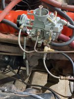
I am relatively certain that the Autolite 1100 we are using has been rebuilt properly and is adjusted reasonably well.

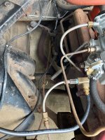
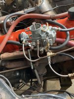
The car will run, but not great. At this point we have traced and fixed all of the vacuum leaks, and when running it is pulling between 17-20 mmhg at the manifold (I installed a T fitting to allow for attaching a gauge that you can see in the pictures).

The car is getting between 3.5 and 4 PSI of fuel (an inline pressure gauge was installed).

I believe that the issue (at least in part, there still could be timing issues, etc.) at this point is the throttle linkage.

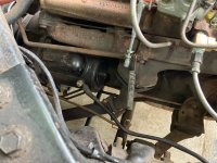
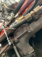
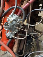
The arm from the linkage across the firewall and to the pedal seems to be sitting very low, resting directly on the exhaust manifold at idle.

We have a new return spring installed (supposedly the correct one for a 200, from NPD) to what appears to be a cobbled wire attachment point on a transmission line (C4 automatic). I have seen some pictures here where the spring is attached through a hole in the flange where the exhaust meets the manifold. There is no such hole on this car, and when hooked into position there, the spring does not supply enough tension for the gas pedal to return properly (it hangs).

When adjusting the throttle linkage, the car either runs with a high idle (around 2K) or stalls out completely, and no amount of adjusting on the carb idle screw has any effect whatsoever. If you hold the carb in position you can get it to run better, but the arm bottoming out on the manifold seems to be preventing us from getting it attached that way. We have an new adjustable linkage for the 200, purchased from CJ pony parts (FM-EA006) but can't seem to get the combination right.

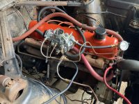
I'm attaching a few pictures of our setup. It has the stock Load-O-Matic distributor.

Any help from the experts would be greatly appreciated. Could this be the problem? Is the linkage bar sitting on the manifold correct?

Thank you all so much!!

Dan and his Dan
 

Attachments

  • image0.jpeg
    image0.jpeg
    557.7 KB · Views: 30
  • image11.jpeg
    image11.jpeg
    1,011.4 KB · Views: 33
  • image10.jpeg
    image10.jpeg
    987.7 KB · Views: 33
  • image9.jpeg
    image9.jpeg
    541.8 KB · Views: 33
  • image8.jpeg
    image8.jpeg
    439 KB · Views: 30
  • image4.jpeg
    image4.jpeg
    530.1 KB · Views: 31
  • image3.jpeg
    image3.jpeg
    524.7 KB · Views: 29
The idle speed adjustment screw is accessed from the driver's side, towards the bottom rear of the carb. It's kind of hard to see and reach. That's what sets the bottom stop on the throttle linkage arm. Yours doesn't look low so much as bent a little bit, in towards the manifold, creating the interference. The new adjustable link is what sets wide open throttle, but you don't want to jam 'er too hard up against the stop. Have someone press the pedal to the floor while you look down the carb throat to see where it is and adjust. Just for reference, my adjustable link is about 4-5/16" ball stud to ball stud. Hard to tell how long a spring under tension is, but yours looks long. The stock attachment point is in the hole in the exhaust flange, and mine fits fine there. Is your flange turned the wrong way so the hole is on the wrong side maybe? You could drill a hole too if there is none.
 
Oh, well there's your problem! The bottom ball stub for the adjustable link is in the wrong hole and on the wrong side. It should be in the end hole on the long rusty linkage arm, and in towards the engine. The spring hooks in the second hole in.
 
See the post above and reference image 10. It looks like a bit of wire is securing the vertical linkage rod.
 
Last edited:
Here’s what mine looks like.

View attachment 17254
Thank you so much, this is greatly appreciated. The spring is supposed to be the correct one for the Ford 200, I'll try again repositioning it to the exhaust flange. It looks like you have an original linkage, ours broke. Any thoughts on how to best get the new threaded rod linkage to attach to the original point on the bar? It didn't look like what is remaining of what was on the end of that bar could be removed to put a new ball stud in.

Again, thank you!
 
See the post above and reference image 10. It looks like a bit of wire is securing the vertical linkage rod.
Yeah, I placed that on there just to be safe, the ball stud does not come through the bar far enough to comfortably tighten down. It is in there pretty good, but wanted some extra insurance. Do you have any insights on where I could source a ball stud with a longer threaded end? I have not had any luck finding one.

Thank you!
See the post above and reference image 10. It looks like a bit of wire is securing the vertical linkage rod.
 
You need to bend that Throttle Linkage Arm back out to the Original location so it's running Paravel again with the Exhaust Manifold having about 3/4 to 1 inch of clearance. If the Ball end is not there anymore you can grind the old Ball end off of this outside of the Throttle Linkage Arm then you can drive it out then you can mount a new bolt on type Ball end in that hole where it's supposed to go this will give the correct action for the Carb Arm too. Might be a lot easier and better to pull out that Pedal Linkage to work on it too. Where are those two home made Vacuum Lines coming off of the Intake Manifold running to?
 
Thank you so much, this is greatly appreciated. The spring is supposed to be the correct one for the Ford 200, I'll try again repositioning it to the exhaust flange. It looks like you have an original linkage, ours broke. Any thoughts on how to best get the new threaded rod linkage to attach to the original point on the bar? It didn't look like what is remaining of what was on the end of that bar could be removed to put a new ball stud in.

Again, thank you!
So there's nothing usable left of the old ball stud? I suppose the hex is rusted off, is there a stub you can grab with a little vice-grip? Use penetrating oil and/or heat too. Tough to bring a drill to bear without removing the whole old bar. I've got a replacement adjustable link laying around just in case. Looks like the threads on the studs are 10-32, but too short to use a nut on the other side of an unthreaded hole. I used to get a lot of weird little hardware stuff at a place called McMaster-Carr. Maybe they've got a little ball stud with longer threads so you could get a nut on.
 
You can grind the old Ball end off of this outside of the Throttle Linkage Arm then you can drive it out then you can mount a new Ball end in that hole where it's supposed to go this will give the correct action for the Carb too. Might be a lot easier and better to pull out that Pedal Linkage to work on it too. Where are those two home made Vacuum Lines coming off of the Intake Manifold running to?
He put a tee in to hook up a vacuum gauge, that musr be the black line. The other looks to be a jury-rigged line for the C4 that takes the scenic route to get there.
 
Yes scenic route indeed it looks like its been hooked up to one of the C4 Trans Cooling Lines much too big for the Vacuum Modulator and then where are the Cooling Lines that should be going to the Radiator?
 
You need to bend that Throttle Linkage Arm back out to the Original location so it's running Paravel again with the Exhaust Manifold having about 3/4 to 1 inch of clearance. If the Ball end is not there anymore you can grind the old Ball end off of this outside of the Throttle Linkage Arm then you can drive it out then you can mount a new bolt on type Ball end in that hole where it's supposed to go this will give the correct action for the Carb Arm too. Might be a lot easier and better to pull out that Pedal Linkage to work on it too. Where are those two home made Vacuum Lines coming off of the Intake Manifold running to?
Thank you. So there should be no interference with the exhaust manifold, and it should be parallel just shy of an inch away? That's helpful!

The car had a fitting into the intake manifold, and then a short steel line, which is connected to the larger steel line that runs to the back of the C4 transmission (I had thought that was original, but I am discovering that although the car has been in my dad's possession since 1969, there are things that are off that must have been done when the car was relatively new, under a previous owner). The diameter of the lines is very similar, and I believe the longer of the lines that runs to the transmission is what remains of the original. The valve at the back of the transmission has been replaced, along with the rubber hose connecting it to the steel line. I can confirm that the whole assembly and line holds vacuum as presently assembled.

The rubber line you see is attached to a T fitting that I temporarily inserted so that I could connect a vacuum gauge to get a manifold vacuum reading. The rubber line runs to a vacuum gauge out of frame that you cannot see in the picture. A properly fitting vacuum cap was placed on the fitting when the gauge and line were removed.

I believe that the cooling lines from the radiator to the transmission are original, or at least routed tightly, and do run from the bottom of the radiator to the C4. I believe they can be seen in some of the pictures, but didn't try to get them in frame.

At this point we have replaced practically everything that is prone to vacuum failure (Carb spacer, transmission valve, distributor connection) and are seeing about 17-20 mmHg of vacuum when the engine is running.

My goal, assuming that it makes sense, is to correct the mechanical throttle linkage irregularities that we have, as best as we can, so that when running at idle, adjustments to the idle mixture screws Autolite 1100 carb (rebuilt original, not a reproduction) are responsive (either visibly or on the vacuum gauge).

Right now the car idle is either running too high, or too low for adjustment to the screw to have any impact, likely because it is not at true idle.

From there we can attempt to investigate the timing and start closing in on a well running 200.

Thank you so much! We greatly appreciate the help.
 
Yes scenic route indeed it looks like its been hooked up to one of the C4 Trans Cooling Lines much too big for the Vacuum Modulator and then where are the Cooling Lines that should be going to the Radiator?
The cooling lines are there, I just didn't try to get them in frame.

I didn't realize that the setup we had for the manifold vacuum to the C4 wasn't stock (fitting into the manifold, short metal line into that fitting, connected to longer metal line, to rubber tube and valve on the C4). My father has had the car since about '69. It has been in my parents garage since '80 (when it was last registered and on the road). We are learning that although the car is mostly stock, there are a small number of "off brand" fixes that were done. This must be one of them as well.

We have replaced the C4 modulator valve and the short rubber tubing from the steel line to the valve. From where the whole assembly connects to the manifold has been confirmed to hold a solid vacuum at this point. Do you suggest that we order a reproduction replacement line from one of the specialty retailers? The goal is that the car run right, we are ok if things aren't quite concours correct.

Thank you again!
 
If the current line is stable and functioning ok, not necessary to change it. If metal lines have a long run without support, they can vibrate and eventually break. Keep an eye on that, both tranny oil and modulator. If you secure it, must be to the engine/bellhousing, not the frame unless there's a rubber section between the metal sections. The rig with the spring attached to the metal line is not a good choice. ☺️
 
If the current line is stable and functioning ok, not necessary to change it. If metal lines have a long run without support, they can vibrate and eventually break. Keep an eye on that, both tranny oil and modulator. If you secure it, must be to the engine/bellhousing, not the frame unless there's a rubber section between the metal sections. The rig with the spring attached to the metal line is not a good choice. ☺️
Thank you. No argument here, that apparently was done a long time ago by people without access to knowledge like what people generously share here on the forum.

Hopefully we can get the mechanical linkage issues sorted, with the spring mounted on the flange (off the line) and working with proper tension.

We will keep an eye on it!
 
My metal lines are long gone. Surprisingly, rubber vacuum lines suck flat in no time. Good quality thick walled fuel line has been working for me for a long time. Here’s my PCV, distributor, and C4 vacuum lines.

View attachment 17259View attachment 17260
Thank you yet again, this is helpful!!

Quick not quite related question. What should be a proper idle range (east coast car, PCV valve but no CA emissions and a C4 automatic) for the car?

Also, I have a new timing light that you are supposed to connect to the coil to be able to get more comprehensive electrical readings than just timing with the light (like idle speed). Do you know which side of the coil you would attach that to? I believe the instructions say the tach side, but I can not see any markings on ours, which could be a yellow topped original.


Thanks!
 
I had to grab my manual for the idle speed. 500-525 RPM in drive with a foot on the brake. I don't have a tach, but I suppose that would be the distributor side of the coil. The other side just sees a steady small DC voltage. So, what kind of manual do you have? The factory manuals are readily available, and very useful. I got by with a small Chilton's manual for 45 years. The Falcon Six Performance Handbook is great for long term project planning, mods, and upgrades.
 
I had to grab my manual for the idle speed. 500-525 RPM in drive with a foot on the brake. I don't have a tach, but I suppose that would be the distributor side of the coil. The other side just sees a steady small DC voltage. So, what kind of manual do you have? The factory manuals are readily available, and very useful. I got by with a small Chilton's manual for 45 years. The Falcon Six Performance Handbook is great for long term project planning, mods, and upgrades.
Thanks again.

I do have a Chilton's manual, I just completely forgot to reference it. Thanks for the reminder, and thank you even more for getting me the information.
 
Yes, the negative side of the coil, which is the distributor side.
 
Back
Top