F15EagleE
New member
Hey all
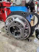
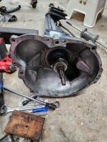
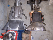
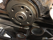
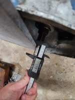
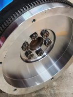
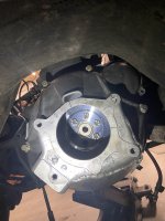
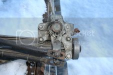
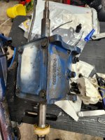
I have a 65 mustang and purchased a Rebuilt c5de motor. When installing my 2.77 , the input shaft is contacting the pilot bushing. It's approximately .25" sticking out... Not sure what's up and hoped someone can shed some light on what's going on here.
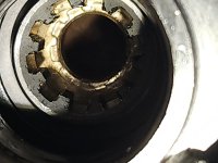
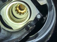
The bushing is .5" wide and driven all the way in. Perhaps there are different crankshaft for the motor?
At this point I'm considering shaving the pilot bushing down to let the transmission fit properly.
I have a 65 mustang and purchased a Rebuilt c5de motor. When installing my 2.77 , the input shaft is contacting the pilot bushing. It's approximately .25" sticking out... Not sure what's up and hoped someone can shed some light on what's going on here.
The bushing is .5" wide and driven all the way in. Perhaps there are different crankshaft for the motor?
At this point I'm considering shaving the pilot bushing down to let the transmission fit properly.
Attachments
Last edited:
")
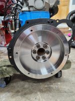
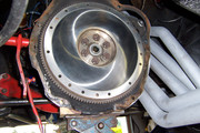
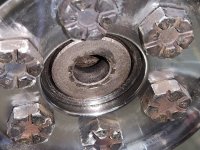
 I think what I was having trouble with was that in that first picture above of those same parts it was such a close up shot that I couldn't see all those parts as well. Anyway everything looks really good on all of your Flywheel and Clutch Assembly install. Otherwise the only other thing I can think of is if the Clutch Disk happened to be turned around the wrong way. I know that isn't likely because if the hub is in backwards it will cause trouble to even be able to bolt down the Pressure Plate. I have never had to cut down a Bushing on one of these before but it should be fine if you have a small 6 or 7 inch Angle Grinder or even a big body type Grinder than you could cut down that Pilot Bushing some so it clears with it installed or else change over to the Roller Bearing.Best of luck.