Have we been going about this all wrong? Discussion welcomed

Wesman07

1K+
VIP
Supporter 2020
Approved Vendor
The 240ci/300ci has a reputation for being “restricted”. So most people in search of better performance put on larger intake manifolds, larger exhausts, larger cams, larger valve and a ported head. The focus is almost always on CFM.

The more I analyze, the more I think we have really been missing the big issue. Airspeed. In stock form the average intake velocity is hitting a max of 200 FPS at 3,500 rpm. A motor like this really wants to be in the 300 FPS neighborhood.

As these typical performance parts get installed, CSA is almost always increased as well. Then we wonder why we can’t make the power we thought it should.

Shouldn’t we be asking ourselves how much CFM do we really need, and focus more on CSA’s?
 
Last edited:
Based on a strong low to midrange daily driver, where in the RPM band do we want 300 fps and does this coincide with max hp rpm?
What cross sectional area would be required to meet this velocity at say 3600, 4500 or even 5000rpm?
Currently building an intake manifold which I know from the pipe max program you use is slightly high on the CSA scale
I absolutely agree that the velocity should be as high as possible without causing a restriction.
The pipe size chosen seemed to match the port so that’s what I used, however I now believe that 1 5/8” od vs 1 3/4 od would be more suitable for stronger torque below 4500 RPM. If you recall you had quoted 250 ft/sec for 2.2 CSA
 

Attachments

  • IMG_1505 2.jpg
    IMG_1505 2.jpg
    1.8 MB · Views: 25
The more I analyze, the more I think we have really been missing the big issue. Airspeed. In stock form the average intake velocity is hitting a max of 200 FPS at 3,500 rpm. A motor like this really wants to be in the 300 FPS neighborhood.
OK. How do you go about increasing the Airspeed for a given port?
 
Based on a strong low to midrange daily driver, where in the RPM band do we want 300 fps and does this coincide with max hp rpm?
What cross sectional area would be required to meet this velocity at say 3600, 4500 or even 5000rpm?
Currently building an intake manifold which I know from the pipe max program you use is slightly high on the CSA scale
I absolutely agree that the velocity should be as high as possible without causing a restriction.
The pipe size chosen seemed to match the port so that’s what I used, however I now believe that 1 5/8” od vs 1 3/4 od would be more suitable for stronger torque below 4500 RPM. If you recall you had quoted 250 ft/sec for 2.2 CSA

Average air speed increases with rpm. For that reason it is best to set air speed off of peak horse power. 300 FPS can be the tipping point for trading horse power for torque gains. 260-285 are more commonly used speeds as there is a very good balance. Most small block V8's are seeing about 285 FPS.

This is what I'm coming up with for a 300ci running at 86% V.E. (14% loss through the manifolds)

3,500 rpm peak hp

Heads (int/ext): (139/110) CFM​

Intake 285- 260 FPS: 1.166- 1.278 CSA​
Exhaust 300 - 240 FPS: 0.877- 1.097 CSA​


4,500 rpm peak hp

Heads (int/ext): (178/141) CFM​
Intake 285- 260 FPS: 1.499- 1.643 CSA​
Exhaust 300 - 240 FPS: 1.128-1.410 CSA​


5,500 rpm peak hp

Heads (int/ext): (218/172) CFM​
Intake 285- 260 FPS: 1.832- 2.010 CSA​
Exhaust 300 - 240 FPS: 1.378- 1.723 CSA​


6,500 rpm peak hp

Heads (int/ext): (257/204) CFM​
Intake 285- 260 FPS: 2.166- 2.373 CSA​
Exhaust 300 - 240 FPS: 1.629- 2.037 CSA​
OK. How do you go about increasing the Airspeed for a given port?

Decrease the CSA and or increase the rpm of the peak hp, which I'm certain you know all about. The point I'm trying to make is in stock form these motors suffer most from a lack of port speed. Its an issue that most people are not seeing or saying. The real challenge is in making these ports and manifolds handle the higher velocities better.
 
Decrease the CSA and or increase the rpm of the peak hp, which I'm certain you know all about. The point I'm trying to make is in stock form these motors suffer most from a lack of port speed. Its an issue that most people are not seeing or saying. The real challenge is in making these ports and manifolds handle the higher velocities better.
The stock ports choke after a certain Airspeed.
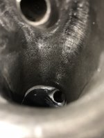
We know that lifting the floor up to the short turn can help.
I'm not sure how decreasing the port CSA would overcome the inherent restriction to flow
 
The stock ports choke after a certain Airspeed.
We know that lifting the floor up to the short turn can help.
I'm not sure how decreasing the port CSA would overcome the inherent restriction to flow
We are on the same page. Raising the floor helps higher airspeeds navigate the turn. The speed of choke is relatively low in this engine, which is the problem and why low airspeeds are used.

CFM is volume of air per minute. If you can increase the speed of the air, you increase the CFM.
 
CFM is volume of air per minute. If you can increase the speed of the air, you increase the CFM.
This is true but if you are stuck with a max airspeed due to design then increasing the CSA including larger valves becomes the next option in increased CFM.
 
This is true but if you are stuck with a max airspeed due to design then increasing the CSA including larger valves becomes the next option in increased CFM.

It is the next best option, but I don’t believe you are stuck with it. I see it as an area that can have major improvements.
 
I'm in favor of a 350 FPS, 300 CFM port but it would require a very straight port design with a moderate CSA.
The Ford Godzilla 7.3 heads have a great high port, high velocity design that flows 300 cfm stock.
 
I have heard very good things about that motor too. On top of being a fast high speed high flowing port, it has a lot of swirl as well. Typically there are trades off with swirl as it takes energy.

I don’t think we will break 300fps without a major design change. But, I think we can get close.

Let’s take the stock head for example. With a good valve job the head should flow enough for a 4,500 rpm peak hp.

If you can raise the floor 0.100” without loosing flow, the average airspeed at peak hp would be about 290ish.

The next thing that can be addressed is the intake manifold. I’m seeing a 0.100” port mismatch with the EFI lower. So, raise the manifold up and re-pin it to the head. Then notch the head to clear a path for the injector.
 

Attachments

  • D937121B-AC70-4115-BB8B-1CDA6332C396.jpeg
    D937121B-AC70-4115-BB8B-1CDA6332C396.jpeg
    1.6 MB · Views: 27
Last edited:
Thanks for the calculations in post #4 Wesman07.

On the velocity issue.
No pushrods to go around must count for something. If we can get a more streamlined guide, wider short side radius and a well formed bowl with better seat approach/departure velocity will go up without increasing CSA. JPierce has some very good drawings of exactly that.
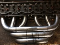
The exhaust port needs to come down in CSA with a curved roof and parallel floor to match( the port would be angled down at the exit instead of being almost perpendicular to the flange). This would get the hot pipes further away from the intake without such an abrupt turn after the flange.
All the headers out there have the pipes expanded at the flange to cover the port so the velocity is high past the valve seat, drops down in the port and speeds up again in the header primaries, especially with the 1 1/2” pipes.
 
Last edited:
We may never get to a perfect velocity, but I believe it’s a good direction to head in. I hope to put this theory to the test soon.

I haven’t spent enough time with the exhaust port to comment too much, but the math seems to indicate that you are correct. Steven did tell me that there is a ceramic epoxy suitable for exhaust ports. And that the he wished these ports were on the 289 v8.

If you get the time. Follow Darin Morgan. He has an excellent way of explaining it all. When he speaks it just clicks for me. There are three or four great videos on YouTube.
 
I would like to further the discussion of the approach towards performance. This time, shifting the focus to valve size.

In order to increase the performance of an engine, we must understand it completely in its original form. So let’s use a completely stock head and valve for example.

The intake side flows 160cfm @ 0.500” lift. The throat is 1.45” diameter, or 1.65 CSA. By dividing the total flow by throat area we know that the port will move 97cfm per square inch.

The 1.78” valve has a circumference of 5.59”. Multiply the circumference by 0.400” valve lift and you get a curtain area of 2.236”. Multiply that by the relatively low cfm per square inch and we get 217cfm. In other words, the numbers are indicating that the head is not valve limited.
 
Last edited:
My best and last 300 build after having some guide problems with a couple early 300 heads. I then located a 300 Propane Forklift Head, I did run a set of stock Size of Valves with a Sérde Valve Job (Radius Cut Seats) along with the 3 angles and back cutting done to the valves. I always though it worked very well however would of been nice if it could of been flowed to see how well it worked. Rest of the 300's short block was stock rebuilder Cast Piston and the Camshaft was Melling RV Grind.

I believe that FTF has mentioned that a 1.90 Intake seems to be optimal along with a 1.60 Exhaust without out doing much if any chamber work on the Carb Heads.
 
So that brings us to the next question. Assuming no race restrictions such as duration or lift limits. If the head is not valve limited, why go to a larger valve?
 
I have heard that a larger valve can flow more because it can give you a better short turn radius when shaped better.
 
Just something to consider:

Peak piston velocity for a 300 six with a 6.21" rod occurs at 74 degrees from TDC.
At 5000 rpm the velocity tangent to the crank throw is (3.98 x pi x 5000)/12 = 5210 fpm.
The piston speed is very close to 5210/ sine 74 degrees = 5420 fpm. (I said close because the right triangle between the rod and crank throw is 72.23 degrees)
The 4.00" piston area is 12.56 sq in or .087 sq ft.

At 5000 rpm the piston is displacing .087 x 5420 = 470 cfm.

Peak airflow corresponding to piston motion at 5000 rpm is 470 cfm.
Since it is linear you can figure peak airflow at other rpms based on the above.
 
Last edited:
That is a good point. If you can safely bring the throat out to about 90 percent of the valve diameter when using a 45 degree seat. Increasing the throat to 90 percent of a 1.78” valve would bring flow up to 195cfm…. In theory.

I think the LS7 is designed with large ports, large valves and a large throat. The key to making that work is in shape of the short turn. It chokes off the throat on purpose. That was touched on one of Darin Morgan’s videos. I didn’t fully grasp the concept. I’ll try and find the video clip.

If SAE determines the most amount of air that can be moved though an orifice is 137cfm/sq in. With our throat moving 97cfm/sqin, it seems to me that is the area that should receive the attention. Address the issue not the symptoms, right?
 
Last edited:
I have heard that a larger valve can flow more because it can give you a better short turn radius when shaped better.
The shape of the short turn does not have a direct relation to valve size. A larger valve flows more at lower lifts because of the curtain area increases. If the throat size stays the same, the larger valve is harder to get the air around it.
 
Back
Top