Build Thread Turbo 250 Mod Log 2.0

"... if I can sneak up on 18 - 20psi without breaking anything,..."
.

real interested in your thorough build, a T3 Draw-Thru setup (Buick) enabled enthusiastic driving until a little too much enthusiasm up @ 1 Bar and oil across windshield. moved to Blow Thru SC'd setup with basically stock 250 better managed, but have set of Forged pistons - probly same ? ...
.
. .
.
.
.

.
.
have fun
 
"... if I can sneak up on 18 - 20psi without breaking anything,..."
.

real interested in your thorough build, a T3 Draw-Thru setup (Buick) enabled enthusiastic driving until a little too much enthusiasm up @ 1 Bar and oil across windshield. moved to Blow Thru SC'd setup with basically stock 250 better managed, but have set of Forged pistons - probly same ? ...
.
. .
.
.
.

.
.
have fun
Those are neat and thoughtful setups, thanks for sharing. I love that picture of the draw through.

What do you think caused that ring/ring land to fail? Not enough gap?

Those are the same forged TRW's that are in this motor. Too bad they don't make them anymore.
 
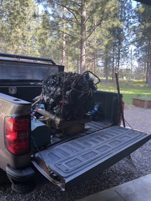
Didn't get a ton done on this project the last couple days but I did pick up an all aluminum L33 that I've been looking for for awhile for the square body project. They're kinda hard to find and my local junkyard had one. Going on the shelf until this is done.

IMG_0101 Large.jpeg

Here are some details I had on my phone I hadn't uploaded yet:

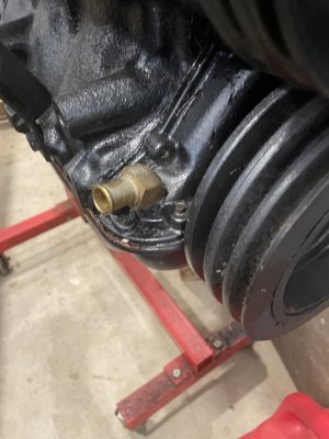
Turbo drain is this 45 degree fitting drilled and tapped through the aluminum timing cover. There's a goldilocks amount of space there on that little rounded corner, and it drops straight into the pan.
IMG_0112 Large.jpeg

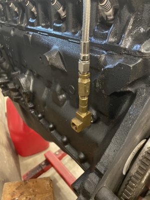
Oil pressure tees and what not. I'm going to add one more tee in place of that coupling, so I can see oil pressure under the hood too. Bottom port is for the inside gauge.

IMG_0110 Large.jpeg

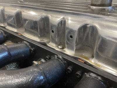
This Edelbrock valve cover came with these two holes in it. Any idea what these were used for? Trying to think if I could do anything useful with them before I plug them. What's that quote about not letting any good crisis go to waste, etc etc.

IMG_0114 Large.jpeg
 
... where does the breather back towards the firewall with the braided silicone hose connect - is that a crankcase breather via the fuel pump block off plate?
.

crankcase pressurization is a basic issue needing to be seriously addressed if heading up in boost . management varies from sophisticated OEM and racing configs' to simple exhaust pipe siphoning...
.

SC'd Mav/Com 250 latest non-sophisticated system for occasional boosts of enthusiasm, VC and Fuel blockoff to cool-cans :
. . .
.
did pick up' an Audi air pump recommended as a forced evac' system triggered by a boost sensor set to needed remedy to play with ...

have fun
 
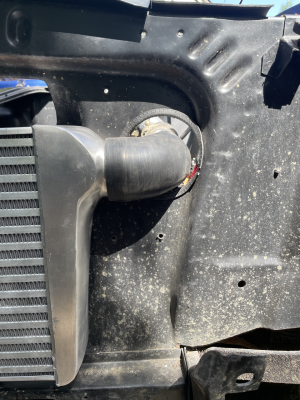
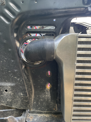
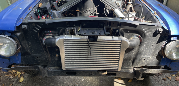
Didn't feel like cutting up the inner fender so I got a shorter intercooler. 25" end to end is widest you can fit inside the inner fenders on a round body, fyi. My other one was 28" and just couldn't make it work.

Used a 4" hole saw like we use to cut out for ceiling boxes in drywall, and then wrapped the holes with some windlace I had from another project (but not before I cut myself test fitting.)

IMG_0140 Large.png
IMG_0141 Large.png


IMG_0142 Large.png
 
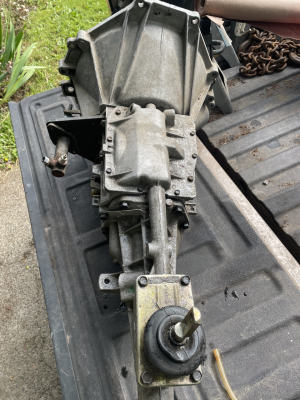
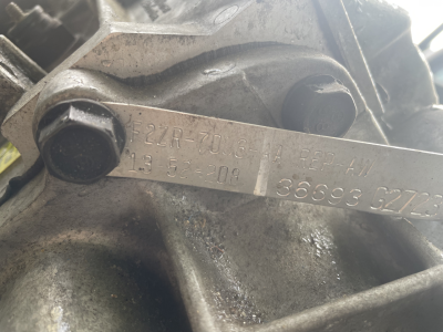
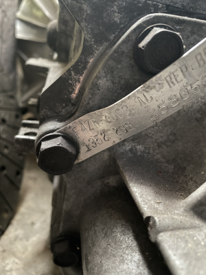
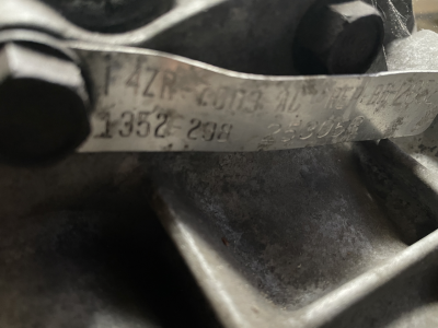
Second one is 1352 - 238:


IMG_0157 Large.png

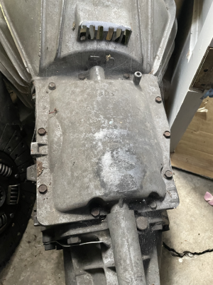
Has a different top cover:

IMG_0156 Large.png

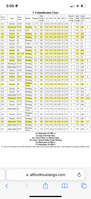
Here's the ID table floating around the interwebs:
IMG_0158 Large.png

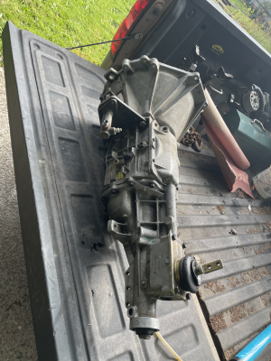
Looks like the first trans, the 13-52-208, it is. It did shift and perform fine when running NA, so we'll see how she holds up.

I'll take the hydraulic slave off it, since this car has a cable clutch setup already. Someone hit me up if you want a hydraulic slave bracket for a T5 that works well in these Falcon based cars. It's waterjet cut 3/8" (1/2"?) plate, with I think a slave from a chevy K10.
 

Attachments

  • IMG_0155 Large.png
    IMG_0155 Large.png
    1.9 MB · Views: 0
Back
Top